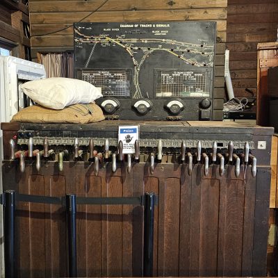
Both the model board and control frame for the former Black River tower on display in the Snoqualmie Depot freight room.
As shown last time, Black River was an important railroad crossing south of Seattle. Here, an interlocking tower protected the meeting place of four separate rail lines. But what is interlocking?
Interlocking is, “An arrangement of signals and signal appliances so interconnected that their movements must succeed each other in the proper sequence.” Josserand, Peter; Forman, Harry Willard (1957). Rights of Trains (5th ed.). More simply, interlocking is a system in which signals and switch points are controlled with interlocked safety mechanisms that prevent dangerous situations.
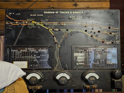
The Black River model board, showing the location of all tracks, signals, and switches. Boards have been attached showing the procedures of what controls to “reverse” to clear movements. If you look closely, you can see where the board has been modified over the years.
The tower operator at Black River had two mechanisms to control: a model board and the control frame. The model board shows the track layout of the crossing, the location of signals and switches, specific blocks, and indicator lights to show when a train is within a block. The operator would use this board to plan and follow train movements.
The other part of the mechanism is the control frame. Some plants used levers to physically throw switches and move signals. Others, like Black River, used electro-mechanical systems where the control frame uses manual levers to operate electric relays. These levers were physically linked together, meaning that the operator would be unable to move a control if it conflicted with an already activated route.
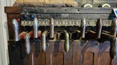
The left side of the Black River control frame. These handles are what the operator would move to activate the corresponding switch or signal. Note the two buttons added for signals 1B and 2B.
The operator would use the model board to identify which switches and signals were needed to clear a line and use the corresponding numbered levers. For example, to route a Union Pacific train from Tacoma to Seattle via the Milwaukee Road and OWRR&N, the operator would need to line the train from block E to G, then on to M and L. This requires seven separate control pulls!
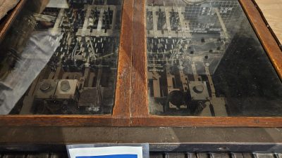
A look inside the Black River control frame. The mechanical interlocking is to the front of the box, connected to the electronic controls.
